.
.Parts of the Camera
Camera Body
Top/Front/Inside
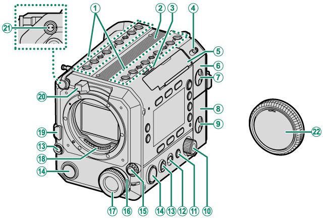
AAccessory mounting screw holes
BHandle attachment mount
CLCD cable release lever
DON/OFF switch
ELCD cable connector cover (detachable)
FBattery-chamber cover
GBattery-chamber cover latch
HMemory card slot cover
IMemory card slot cover latch
JSelector dial
K[BACK] button
LLock switch
M[GRAB] button
N[REC] button
OFocus mode selector
PMulti-function selector dial
QMulti-function dial
RLens signal contacts
SLens release button
TLens lock lever
UDC OUT 12 V connector
VBody cap
Top/Front/Inside (Continued)
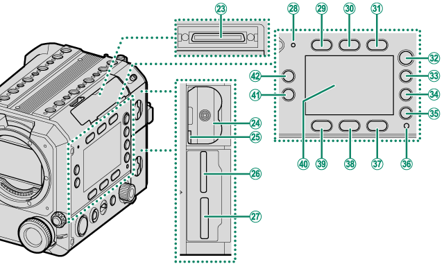
WLCD cable connector
XBattery chamber
YBattery latch
ZMemory card slot 2
(for SD memory cards)
aMemory card slot 1
(for CFexpress Type B cards)
bMicrophone
cScreen button 1
dScreen button 2
eScreen button 3
f[HOME] button
g[USER] button
h[PLAY] button
i[MENU] button
jIndicator lamp
kScreen button 6
lScreen button 5
mScreen button 4
nSide monitor
o[Fn2] button
p[Fn1] button
Outside/Bottom
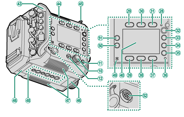
qCable protector (detachable)
rExhaust vent
sMeasure hook
tSerial number plate
uAir intakes
vTripod plate attachment holes
wSpeaker
x[Fn4] button
y[Fn3] button
zLENS Connector (12-pin)
Back
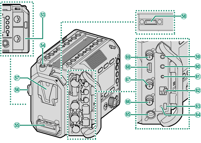
0Wi-Fi antenna (internal)
1Release button
2V-mount battery attachment terminal
3V-mount battery release button
4V-mount battery attachment mount
5Handle connection terminal
6Microphone connector (φ 3.5 mm)
7Headphone jack (φ 3.5 mm)
8Remote release connector (φ 2.5 mm)
9LAN connector
AUSB connector (Type-C)
BHole to screw USB cable
CDC IN connector
DGENLOCK connector (BNC type)
ETC IN/TC OUT connector (BNC type)
FHDMI OUT connector (Type A)
GSDI OUT connector (BNC type)
LCD Monitor
See page “aAttaching the LCD Monitor” for instructions on how to attach the LCD monitor and LCD attachment, and how to attach them to the camera body.
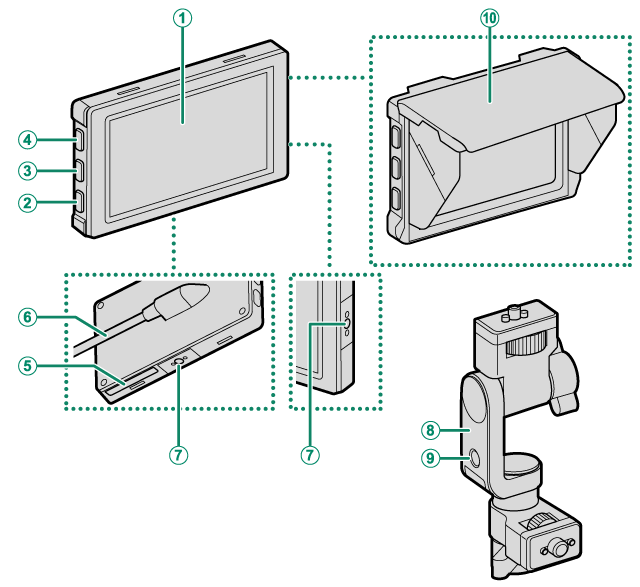
ALCD monitor
Touch screen
B[DISP] (display) button
C[Fn7] button
D[Fn6] button
ESerial number plate
FLCD cable
GAccessory mounting screw holes
HLCD attachment
IAccessory mounting screw hole
JLCD monitor hood
Handle
See page “aAttaching the Handle” for instructions on how to attach the handle to the camera body.
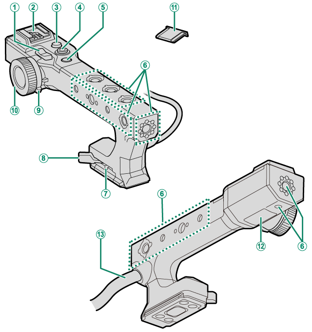
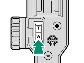
AZoom lever
BHot shoe
C[REC] button
DFocus stick (focus lever)
E[Fn5] button
FAccessory mounting screw holes
GLock lever adjustment screw
HLock lever
IMulti-function selector dial
JMulti-function dial
KHot shoe cover
LSerial number plate
MHandle cable
- Side Monitors
- [REC] Button
- [GRAB] Button
- Focus Mode Selector
- Multi-Function Dial
- Lock Switch
- The Indicator Lamp
- Accessory Mounting Screw Holes/Tripod Plate Attachment Holes
- LCD Cable Connector Cover (Detachable)
- Measure Hook
- Air Intakes/Exhaust Vent
- Wi-Fi Antenna (Internal)
- Handle
- LCD Monitor
- The Serial Number Plates
Side Monitors
You can use the side monitors to check the shooting settings and select files to play back. Use the buttons and dials around the monitors to switch displays, change settings, and operate the menu.
The side monitors are located on both the inside and outside of the camera body. The side monitors, buttons, and dials on the left and right sides are identical. Operating a button or dial on either side will change the display on both monitors.
Use [LCD SETTING] > [SIDE MONITOR BRIGHTNESS] in [SET UP] to adjust the brightness of the side monitors.
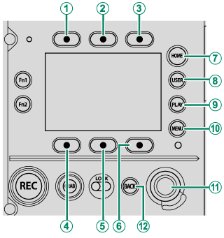
Inside
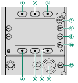
Outside
AScreen button 1
BScreen button 2
CScreen button 3
DScreen button 4
EScreen button 5
FScreen button 6
G[HOME] button
H[USER] button
I[PLAY] button
J[MENU] button
KSelector dial
L[BACK] button
[HOME] Button
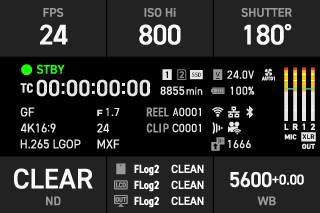
Press [HOME] to display the main shooting settings on the side monitors (aShooting Settings).
[USER] Button
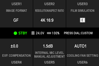
Press [USER] to display the pre-assigned functions on the side monitors (a[USER] Function).
[PLAY] Button
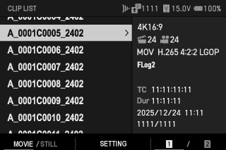
Press [PLAY] to display the playback settings on the side monitors. You can select files to be played back on the LCD monitor and configure the playback settings (aThe Playback Display).
[MENU] Button
Press the [MENU] button to display the menu on the side monitors. You can configure the shooting settings and camera settings (aThe Menus).

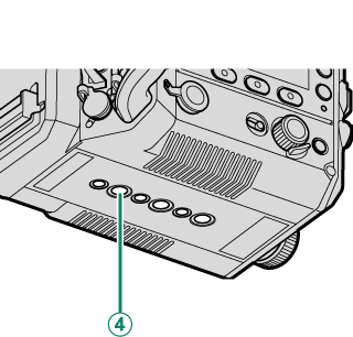
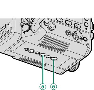
Screen Buttons
Press the screen buttons (1-6) to use the functions indicated above or below the buttons or to change the assigned settings.
AScreen button 1
BScreen button 2
CScreen button 3
DScreen button 4
EScreen button 5
FScreen button 6

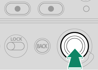
Selector Dial
Use the selector dial to operate the menu and playback settings.
Rotate the dial left or right to move the cursor.
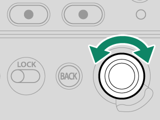
Press the center to select an item.
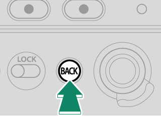
[BACK] Button
Press [BACK] on the playback settings or menu display to return to the previous display without changing the settings.
Touch Screen Mode on the Side Monitors
When entering text such as a password, an on-screen keyboard will be displayed on the side monitors. Tap the screen or press the screen buttons to enter characters.

The functions of the screen buttons are as follows.
| Button | Description | |
|---|---|---|
 |
Move left (Screen button 1) |
Move the cursor one character to the left. |
 |
Move right (Screen button 2) |
Move the cursor one character to the right. |
 |
Delete (Screen button 3) |
Delete one character before the cursor. |
| [CANCEL] | Cancel (Screen button 4) |
Exit text entry without saving changes. |
 |
Switch character type (Screen button 5) |
Switch between uppercase letters, lowercase letters, and symbols each time the button is pressed. |
| [DONE] | Done (Screen button 6) |
Save changes and exit text entry. |
The layout and types of keys on the display vary depending on the item being entered.
[REC] Button
Press [REC] to start movie recording and the button will light in red. Press the button again to stop recording and it will turn off.
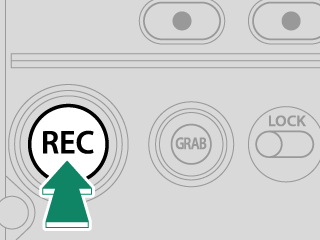
During playback, pressing the button will not start recording.
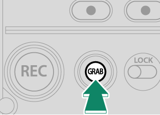
[GRAB] Button
Press [GRAB] to capture a still image from a movie (aSaving Still Images).
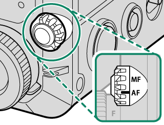
Focus Mode Selector
Use the focus mode selector to switch the focus modes (aAutofocus, aManual Focus).
Multi-Function Dial
Rotate the multi-function dial to adjust settings for the function selected with the multi-function selector dial.
Multi-function dial
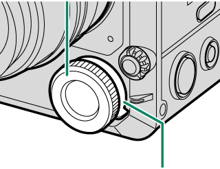
Multi-function selector dial
The functions that can be adjusted with the multi-function dial are as follows:

| Multi-function selector dial | Description |
|---|---|
| [F] (focus) |
You can adjust the focus when using manual focus. |
| [Z] (zoom) |
You can adjust zoom when using a lens that supports power zoom. aZoom |
| [I] (iris) |
While [RECORDING] > [IRIS] is set to an option other than [AUTO], when a lens with no aperture rings is used or when the lens aperture ring is in the [C] position, you can adjust the iris. aIris |
| [ND] (ND filter) |
You can adjust the ND filter density when [ON] is selected for the ND filter. |
| [OFF] | Multi-function dial operation will be disabled. |
Lock Switch
Use the lock switch to lock buttons and dials.
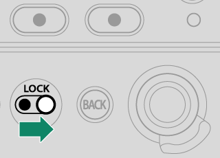
- Use the inside lock switch to lock the buttons and dials on the inside, the focus mode selector, and the multi-function dial.
- Use the outside lock switch to lock the buttons and dials on the outside, and the [REC] and [GRAB] buttons on the front.
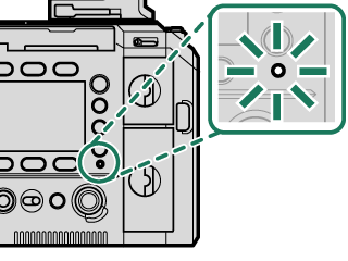
The Indicator Lamp
Camera status is shown by the indicator lamp.
| Indicator lamp | Camera status |
|---|---|
| Blinks green and orange | Uploading selected files via the network when the camera is off. |
| Glows orange | Recording files. No additional files can be taken at this time. |
| Blinks red | Lens or memory error. |
Warnings may also appear in the display.
The indicator lamp shows the status of its connection to computers, Frame.io, and the like (aCamera Indicator Lamp Display).
While the function button to which [AF-ON] is assigned is pressed, the indicator lamp glows or blinks green.
Accessory Mounting Screw Holes/Tripod Plate Attachment Holes
Accessory Mounting Screw Holes (on the Camera Body)
The supplied LCD attachment and other optional accessories can be attached to the accessory mounting screw holes on the top of the camera (aAttaching the LCD Monitor). The dimensions are as follows:

Accessory mounting screw holes
Screw type: 3/8-16UNC (x 8)
Screw hole depth: 6 mm
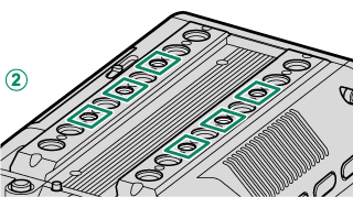
Accessory mounting screw holes
Screw type: 1/4-20UNC (x 6)
Screw hole depth: 6 mm
Accessory mounting screw holes
Screw type: 3/8-16UNC (x 4)
Screw hole depth: 10.5 mm
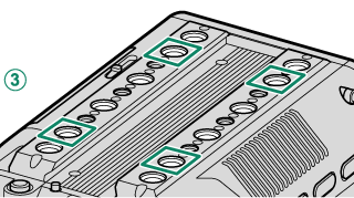
Tripod Plate Attachment Holes
Optional tripod plates or bridge plates can be attached to the tripod plate attachment holes on the bottom of the camera. The dimensions are as follows:

Tripod plate attachment hole
Screw type: 1/4-20UNC (x 1)
Screw hole depth: 8 mm

Tripod plate attachment hole
Screw type: 1/4-20UNC (x 1)
Screw hole depth: 12 mm

Tripod plate attachment hole
Screw type: 1/4-20UNC (x 1)
Screw hole depth: 11 mm
Tripod plate attachment hole
Screw type: 3/8-16UNC (x 1)
Screw hole depth: 12 mm
Tripod plate attachment hole
Screw type: 3/8-16UNC (x 2)
Screw hole depth: 11 mm
LCD Cable Connector Cover (Detachable)
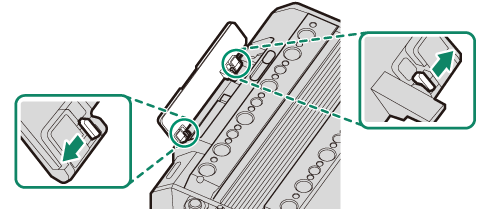
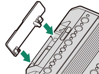
The LCD cable connector cover can be removed if the cover interferes with the rig or accessories when attaching them.
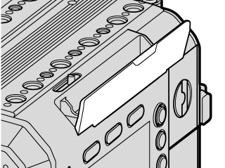
To remove the LCD cable connector cover, pull the orange levers inside the cover as shown.
Attach the LCD cable terminal cover when you do not use the LCD monitor.
Attaching the LCD Cable Connector Cover
Press in the LCD cable connector cover as shown to attach it.
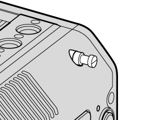
Measure Hook
The hook indicates the position of the image sensor. Attach the tip of a measure to the measure hook to measure the exact distance between the image sensor and the subject.
Air Intakes/Exhaust Vent
Do not cover the air intakes or exhaust vent with tape or other materials or place any obstructions near them. Failure to observe this precaution may reduce cooling performance or damage the camera.
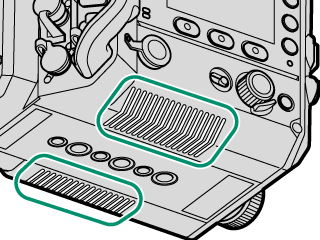
Air intakes
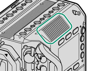
Exhaust vent
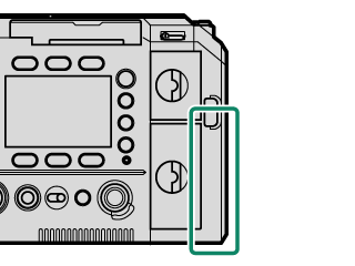
Wi-Fi Antenna (Internal)
The camera has a Wi-Fi antenna inside, so covering it with your hand or metal objects may interrupt Wi-Fi communication.
Handle
Attach the handle to the camera body to set the focus area with the focus stick (focus lever) or operate the zoom with the zoom lever.
Attach the handle to the handle attachment mount on the top of the camera body (aAttaching the Handle).
Focus Stick (Focus Lever)
Tilt or press the focus stick to select the focus area. The focus stick can also be used to navigate the menus.
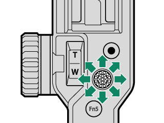
Zoom Lever
You can adjust zoom with the zoom lever when using a lens that supports power zoom. The zoom speed changes depending on how far you press the zoom lever (aZoom).
Accessory Mounting Screw Holes (on the Handle)
The supplied LCD attachment and other optional accessories can be attached. The dimensions are as follows:
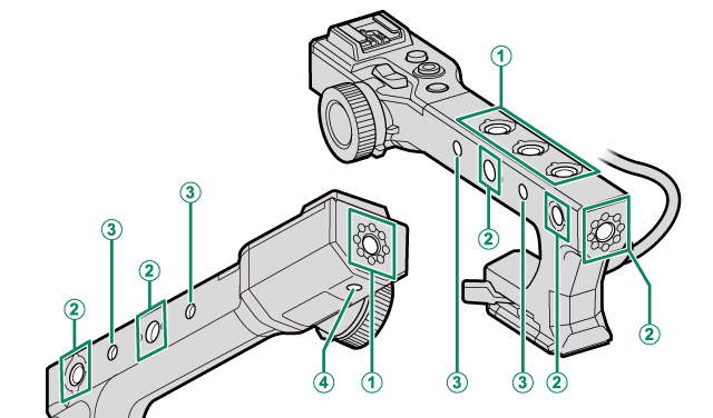
AAccessory mounting screw holes
Screw type: 3/8-16UNC (x 4)
Screw hole depth: 12.5 mm
BAccessory mounting screw holes
Screw type: 3/8-16UNC (x 5)
Screw hole depth: 12 mm
CAccessory mounting screw holes
Screw type: 1/4-20UNC (x 4)
Screw hole depth: 8 mm
DAccessory mounting screw holes
Screw type: 1/4-20UNC (x 1)
Screw hole depth: 7 mm
LCD Monitor
Connect the LCD monitor to the camera to check the shooting display and play back recorded movies. The LCD monitor can also be used as a touch screen during recording and playback (aLCD Monitor Touch Controls).
Attach the LCD monitor to the accessory mounting screw holes on the top of the camera body or handle (aAttaching the LCD Monitor).
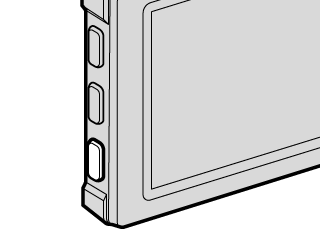
[DISP] Button
Press [DISP] to enable or disable the information display on the LCD monitor. Press and hold the button to flip the LCD monitor display vertically or horizontally.
Accessory Mounting Screw Holes (on the LCD Monitor)
Optional accessories can be attached. The dimensions are as follows:
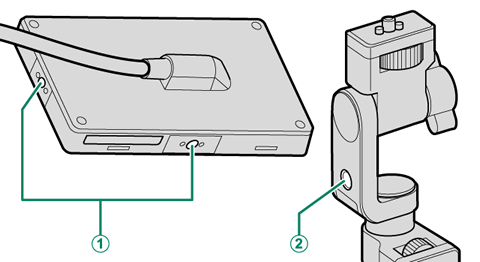
AAccessory mounting screw holes
Screw type: 1/4-20UNC (x 2)
Screw hole depth: 7.5 mm
BAccessory mounting screw holes
Screw type: 1/4-20UNC (x 1)
The Serial Number Plates
Do not remove the serial number plates, which provide the CMIIT ID, serial number, and other important information.
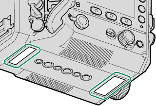
Camera body
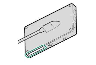
LCD monitor
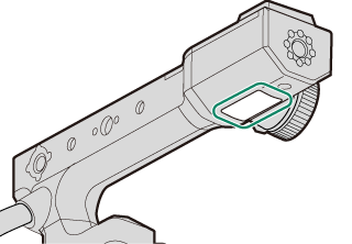
Handle